 en
en русский
 Deutsch
 日本語
日本語 Español
 简体中文
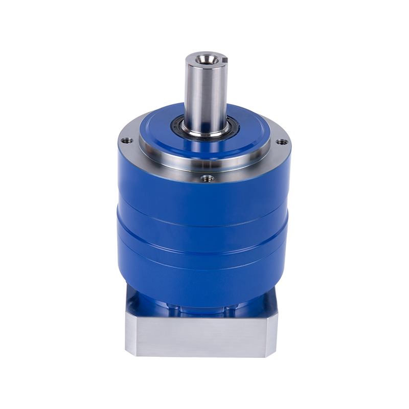
简体中文Servo Motor MKT Precision Planetary Reducer
Cat:MK series planetary reducer
Meet the needs of customers with high precision requirements for semiconductor devices, automation equipment, machine tools, etc.Applicable to: Door d...
See DetailsContent
High Speed Reduction Gearboxes are precision components critical to industries like energy, petrochemicals, and heavy machinery, where they connect high-speed prime movers (like turbines or electric motors) to slower, high-torque driven equipment (like compressors, pumps, or mills). Their core function is to reduce a very high input rotational speed to a usable output speed while proportionally increasing torque. A fundamental design question engineers face is: How many reduction stages are needed to achieve this? The answer is not a simple rule of thumb but a careful optimization exercise influenced by mechanical, thermal, and economic factors.
The most immediate factor is the magnitude of the required speed change, expressed as the Total Reduction Ratio (i).
Every meshing gear pair introduces power losses due to friction, sliding, and churning of lubricating oil. The number of stages has a direct, cumulative impact on overall efficiency.
The physical size and shape of the gearbox are often dictated by its installation environment.
This is a core engineering consideration. Gears must withstand bending stresses at the tooth root and contact (Hertzian) stresses on the tooth flank.
High-Speed Reduction Gearboxes are significant sources of heat due to mechanical losses. This heat must be managed to prevent oil degradation, component distortion, and reduced bearing life.
Ultimately, engineering is an exercise in optimized cost for performance.
Many gearbox manufacturers utilize modular or platform-based designs. They may have a set of standardized gear stages (e.g., a “5:1 ratio module”) that can be combined. The chosen stage count may be influenced by the closest available combination of these standard modules to achieve the desired ratio efficiently, leveraging proven designs to reduce cost and lead time.
Determining the number of reduction stages in a High-Speed Reduction Gearbox is not a sequential checklist but a iterative, systems-engineering process. The total required ratio sets the starting point. From there, designers must balance:
The final design represents an optimal compromise where adding another stage would create more problems (inefficiency, cost, heat) than it solves, and removing a stage would make the remaining stages impossibly large or weak. It is this intricate balance that makes the design of a reliable High-Speed Reduction Gearbox a specialized feat of mechanical engineering, one that quietly underpins the reliable operation of critical industrial infrastructure worldwide.

Meet the needs of customers with high precision requirements for semiconductor devices, automation equipment, machine tools, etc.Applicable to: Door d...
See Details
Industry- product lineupApplicable to: Door drive (planetary, coaxial shaft)MKL Precision Planetary Reducer lies in its multi-size segment selection c...
See Details
Meet the needs of customers with high-precision requirements for semiconductor devices, machine tools, etc.MKG reducer meets the various needs of cust...
See Details
Ball bearings, orthogonal axis, more flexible installationMKEB Planetary Reducer stands as a testament to advancements in planetary gear technology, f...
See Details
Helical gear design, high bite rate, smooth operation, low noise, low backlash. The sun gear output shaft bearing is designed directly in the arm to e...
See Details
At the heart of the RCIV ring gear output AGV special planetary reducer is a sophisticated design that features a distinctive ring gear output configu...
See Details
High-performance output shaft type planetary reducer, with high rated speed and high dynamic application, adopts lightweight design and high-efficienc...
See Details
The planetary reducer adopts a planetary gear transmission structure, which has high transmission efficiency, and the single solid shaft design can re...
See Details
The worm bevel double output shaft type planetary reducer uses a combination of worm gear transmission and planetary gear transmission to improve the ...
See Details
The hollow-type high-precision spiral bevel gear reducer is specially designed. The hollow design makes the center space of the reducer empty and can ...
See DetailsMAKIKAWA-MOTION TECHNOLOGY (ZHEJIANG) CO., LTD. @ All rights reserved

Custom High Precision Planetary Gearbox Reducer Manufacturers